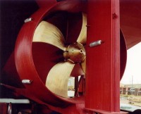
How a Marine Nozzle Works
|
To obtain the most thrust, a
propeller must move as much water as possible in a given time. A nozzle will
assist the propeller in doing this, especially when a high thrust is needed at a
low ship speed. As we already know, as the propeller blades rotate in the water,
they generate high-pressure areas behind the each blade and low pressure areas
in front, and it is this pressure differential that provides the force to drive
the vessel. However, losses occur at the tip of each blade as water escapes from
the high pressure side of the blade to the low pressure side, resulting in
little benefit in terms of pushing the vessel forward. The presence of a close
fitting duct around the propeller reduces these loses by restricting water flow
to the propeller tips. |
 |
|
The cross sectional area at the entrance of the nozzle is greater than
at the trailing throat. Since the water density is constant, the water
must accelerate from one to the other. Hence the water is already moving
faster as it reaches the propeller than it would on a conventional open
propeller. Therefore, more water is moved and more thrust created for the
same input power and torque.
However, there are efficiency gains to be
made even when it comes to the nozzle design. Some designs will drag as
the speed of the advance increases. With the Kort nozzle design, this drag
becomes more significant at higher speeds and can eventually reduce the
overall thrust gain to zero. The coefficient of drag is over 17 times less
with the Rice speed nozzle than the Kort 19A design. |
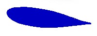
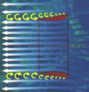
Rice Speed Nozzle Profile
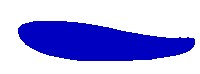
Rice Thrust Nozzle Profile |
| The section of a Rice-Speed Nozzle
was developed from air wing sections displaying highest lift/lowest drag
properties. When nozzle sections of Kort 19-A and Rice-Speed are compared in
Figure 2 below, the drag coefficient of a Rice-Speed Nozzle is 17 times lower
than Kort 19-A type. |
 |
| Figure 2. Comparison of Drag
Coefficient Between Kort and Rice Nozzles |
Kort Nozzle 19a cd = 0.17
 |
Rice Nozzle cd = 0.01
 |
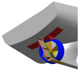
OPERATIONAL ANALYSIS OF A RICE SPEED
NOZZLE
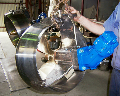
Figure 3 Transverse View of Rice Nozzle.
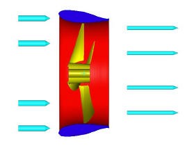 |
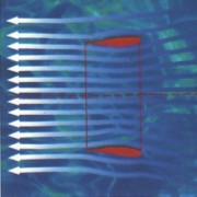
Due to the design (Figure 3), the propellers working
area in the centre of nozzle, is approximately 40% smaller than the area
of the nozzle entrance. This results in an increase of water speed and a
decrease of internal pressure in relation with external pressure - which
remains more or less constant. Because of this pressure difference, a force
P (Figure 4) is created on the external surface of the nozzle that is
always perpendicular to this surface.
Due to the design of the outside trailing end part of the nozzle, the
horizontal component of this force P creates an additional forward thrust
on the nozzle; increasing the total thrust of the vessel. |
Figure 4 Pressure Differences Creates Additional Forward
Thrust.
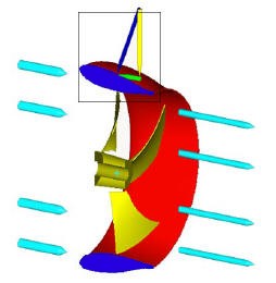 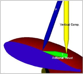
Up to 40% of the total thrust is generated by the nozzle itself and is
transmitted directly to the hull.
|

|